GD&T (Geometric Dimensioning and Tolerancing)
GD&T is a key tool that enhances quality and productivity by standardizing communication between product design and manufacturing. ASME Y14.5 serves as the international standard for GD&T, maximizing the clarity and consistency of dimensioning and tolerancing to effectively convey design intent.
This document systematically introduces the core concepts of ASME Y14.5—such as datums, feature control frames, and tolerance zones—and explains how GD&T is applied in real-world automotive parts quality control through specific case studies. The focus is particularly on GD&T’s practical benefits, including ensuring assemblability, meeting functional requirements, and improving measurability.
Through this, readers will understand that GD&T is more than just a set of drawing symbols—it is a strategic tool for securing quality across the entire design-manufacturing-inspection process.
Overview of ASME Y14.5
ASME Y14.5 is a standard by the American Society of Mechanical Engineers (ASME) for Geometric Dimensioning and Tolerancing (GD&T). It defines shape, tolerances, datums, symbols, and interpretation methods clearly for use on drawings and digital models.
The purpose is to effectively communicate design intent, improve consistency and quality in manufacturing and inspection processes, and help reduce costs and shorten lead times.
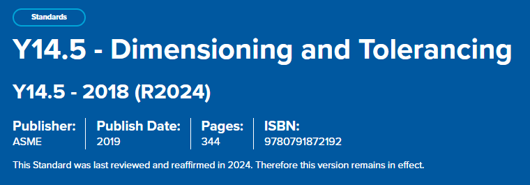
The latest revision is ASME Y14.5‑2018, which has been updated to support CAD and Model-Based Definition (MBD) environments. Key updates include the concept of Feature of Size, enhanced composite position tolerances, strengthened profile tolerances, and clarification of coordinate system interpretation.
Key Elements and Symbols
ASME Y14.5 is broadly categorized into:
- Form: Straightness, flatness, circularity, cylindricity
- Profile: Line profile, surface profile
- Orientation: Angularity, perpendicularity, parallelism
- Location: Position, concentricity, symmetry
- Runout: Circular runout, total runout
The table below categorizes the symbols shown in the accompanying image:
| Category | Geometric Characteristic | Symbol Examples |
|---|---|---|
| Form | Straightness, Flatness, Circularity, Cylindricity | – |
| Profile | Profile of a Line, Profile of a Surface | – |
| Orientation | Angularity, Perpendicularity, Parallelism | – |
| Location | Position, Concentricity, Symmetry | – |
| Runout | Circular Runout, Total Runout | – |
- Datum: A theoretically perfect point, line, or plane used as a reference to control other features or tolerances. Datums are essential for constraining the six degrees of freedom (translation and rotation) of a part.
- Feature Control Frame (FCF): A rectangular frame that specifies geometric tolerances, datums, modifiers, and values to precisely define GD&T requirements.
Structure of ASME Y14.5 (Section Breakdown)
- Sections 1–4: Cover drawing symbols, general rules, and datum selection criteria.
- Sections 5–12: Provide detailed specifications by tolerance type:
- Section 5 – Form: Straightness, flatness, circularity, cylindricity
- Section 6 – Orientation: Angularity, perpendicularity, parallelism
- Section 7 – Location: Position, concentricity, symmetry
- Section 8 – Profile: Line and surface contour control
- Section 9 – Runout: Surface variation control for rotating features
- Sections 10–12: Additional supporting requirements
Core Concepts You Must Know
| Concept | Description |
|---|---|
| Datum | A theoretical reference point, axis, or plane used to locate features. |
| Feature of Size | A physical portion of a part with size (e.g., hole, shaft). |
| Tolerance Zone | The 3D space within which a feature must lie. |
| MMC / LMC / RFS | Material condition modifiers: Maximum, Least, Regardless of Feature Size. |
| Virtual Condition | The worst-case boundary of a feature considering size and tolerance. |
| Feature Control Frame | A rectangular box that defines the tolerance type, value, and datum references. |
Types of Tolerances
1. Form Tolerances (No datum required)
- Straightness: Line element must be straight.
- Flatness: Surface must lie between two parallel planes.
- Circularity: Circular elements must be concentric.
- Cylindricity: Entire cylindrical surface must be within tolerance.
2. Orientation Tolerances (Datum required)
- Parallelism: Feature must be parallel to datum.
- Perpendicularity: Feature must be 90° to datum.
- Angularity: Feature must be at a specified angle.
3. Location Tolerances
- Position: Controls location of features (e.g., holes).
- Concentricity: Controls median points of diametrically opposed elements.
- Symmetry: Controls center plane alignment.
4. Profile Tolerances
- Profile of a Line: Controls 2D shape.
- Profile of a Surface: Controls 3D shape.
5. Runout Tolerances
- Circular Runout: Controls circular elements relative to datum axis.
- Total Runout: Controls entire surface.
Drawing Interpretation Essentials
- Basic Dimensions: Theoretically exact; shown with a box.
- Reference Dimensions: For information only; shown in parentheses.
- Dimensioning Methods:
- Rectangular or polar coordinates.
- Tabular dimensioning for repetitive features.
- Implied Angles: 90° or 0° assumed unless specified.
- Unit Systems: SI (mm) preferred; U.S. customary (inches) allowed.
Inspection & Quality Control Guidelines
- Datum Reference Frames: Establish 3 mutually perpendicular planes (X, Y, Z).
- Datum Feature Simulators: Physical or theoretical tools used to replicate datum features.
- Material Condition Modifiers:
- RMB: Datum applies regardless of size.
- MMB / LMB: Datum applies at maximum/least material boundary.
- Free-State Condition: Applies to flexible parts unless restrained.
- Projected Tolerance Zones: Used for fasteners to avoid interference.
Summary
ASME Y14.5 is the core standard for GD&T, enabling clear expression of design intent and consistent interpretation across manufacturing and inspection processes.
The 2018 revision is optimized for CAD and MBD environments, with major updates including enhanced profile tolerancing, composite position tolerances, and improved datum and degrees-of-freedom interpretation.
The symbols presented in the diagram classify the five main types of geometric characteristics controlled by GD&T: form, orientation, location, profile, and runout.


